|
The original motors used in this platform had no electromechanical brakes, which is fine,
as long as nothing unexpected happens and the platform is always moved all the way down
in a controlled manner before turning off power. However, if power is turned off while
the platform is still in a lifted position, it just falls down and may even cause hardware
damage. I therefore replaced the original motors with versions that have brakes. These brakes
prevent the motor axle from rotating if there is no power. Only if 24V is applied to the brake,
it disengages and the axle can rotate freely. So in case of an unexpected power loss the brakes
will engage and keep the platform at its current position.
According to specs the electromechanical brake of a single motor draws 0.6A at 24V. All six of them add up to
3.6A, or a total power consumption of 86.4W!
The brakes also get pretty warm, up to 42°C (depending on the ambient temperature). At that
temperature the current goes down to about 0.5A, which reduces the overall power consumption to 72W.
But that is still pretty much, and having the motors get that warm seems like a total waste of energy.
There is, though, a way to reduce the power necessary to operate the brakes.
The brakes are electro magnets, which work against a spring that holds them in the engaged
position if there is no power. Once the brake is released, the voltage can be reduced quite
a bit and the brake still remains disengaged. The brake needs a voltage of above 16.8V to
disengage, and can go down as low as 4.5V before it engages again.
We need 24V/3.6A to release the six brakes. But only for a brief moment! After that, we can
reduce the voltage to, say, 12V. That results in a quarter of the power (0.9A or 21.6W), and with each
coil only consuming 0.3A the temperature only goes as high as 30°C. That's 12° less
that at full power!
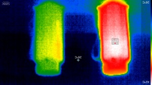 | This infrared image shows on the left side a motor with its brake continuously supplied with 24V. The motor on the right had its brake disengaged with 24V and after that the supply was reduced to 12V. While the left brake heats up to 42°C, the right one stays at a much cooler 30°C. Measured after 2.5 hours of being turned on, at an ambient temperature of about 25°C and 40% humidity. |
However, there's no easy way to make a 24V power supply switch down to 12V.
But we can change the configuration of the brake coils. Instead of connecting all six
of them in parallel, we can make two sets of three coils in parallel, and connect these
sets serially. That will result in each coil getting 12V.
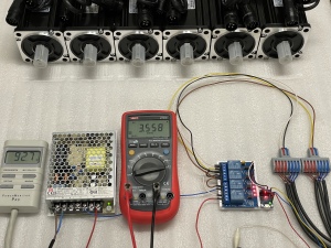 | This test setup shows the 24V power supply [1] I am using, together with a 4 channel 5V relay module [2] and a Digispark Attiny85 [3] micro controller. Power distribution to the brakes is done via two connection clamps [4], which also hold the flyback diodes [5]. The meter on the left shows the total power consumption from the main outlet, and the one in the middle displays the current on the 24V line. Note the four red LEDs on the relay board, indicating that the brakes are in 24V mode, using 3.558A (92.7W). The power meter shows a little more than the theoretical value, which is due to the internal power used by the 24V supply. |
 | After one second the relay board switches into 12V mode, which cuts the required power by a factor of four, thus saving 75% of energy! |
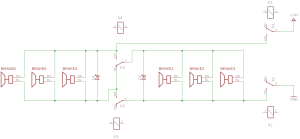 | The schematic of the brake control. The six brakes are divided into two groups of three. K1 and K2 turn the 24V power supply on/off (this could be done with a single relay, or the two could be connected in parallel, I just chose this way). If K3 and K4 are ON, all brakes are in parallel and get the full 24V, so they disengage. If K3 and K4 are OFF, the two sets of brakes are connected serially, thus giving them only 12V. The two flyback diodes are necessary to make sure the brakes don't engage during the brief moment when K3 and K4 switch and the current flow gets interrupted. They also reduce the sparks on the relay contacts when power is turned off. I used Schottky diodes that were left over from an earlier project, any other suitable diodes should do just as well. |
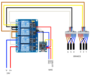 | The wiring of the brake control. M4S ist the "Motion4Sim" controller (any other controller that has an "active low" pin for controlling motor brakes should work just as well). The code for the Attiny85 can be found here. |
 | To hold the relay module and the Attiny85 board I 3D-printed this little part. It allows for easy replacement should one of them fail. Here's the FreeCAD and STEP files, in case you want to use it. |
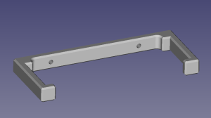 | The power supply is held by two brackets. It can also be easily swapped in case of a failure (FreeCAD and STEP files). |
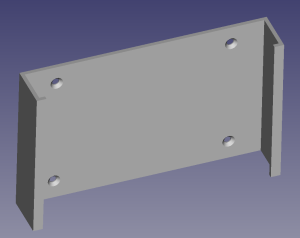 | To make room for the additional hardware I had to replace the wooden brackets I originally used in the control box with a more compact version (FreeCAD and STEP files). |
 | Here's a view of the control box with the 3D printed brackets installed. On the left and right side there are the connection clamps for the brakes. |
 | Power supply and controls for the brakes. |
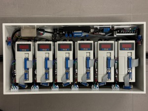 | The newly refurbished control box. When I ordered the new motors with brakes, I also got new (white) servos. |
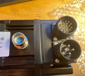 | When I ordered the new motors, I wanted to have them with the connectors directly mounted to the casing, as in this picture... |
 | ...unfortunately they sent me the version with cables and plugs. I didn't return them (would have taken several more weeks), but rather designed a fixture (FreeCAD and STEP files) and clips (FreeCAD and STEP files) to keep the plugs and cables in place. The original Allen screws that held the cover of the cables were replaced with these [6]. |
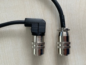 | I didn't like the way the plugs for the power to the brakes stuck out like a sore thumb, with sharp edges at the screws, so I designed a cover that transforms it into a 90° version (FreeCAD and STEP files). The two halves of the cover are held together with M2x16 Allen screws from this set [7] (unfortunately there were no 14mm screws, which would have been a better fit). |
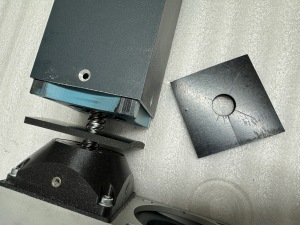 | While I had the actuators disassembled to install the new motors, I also inserted a 75x75mm piece of rubber (cut from a 4mm rubber strip [8]) with a 20mm hole for the ball screw. This is to prevent the actuators from crashing hard against the bottom in case something goes wrong - which shouldn't happen any more, thanks to the brakes, but you never know. |
Links
[1] https://www.amazon.de/dp/B06XWR8RGJ
[2] https://www.amazon.de/dp/B00E0NSORY
[3] https://www.amazon.de/dp/B08PB8Z1BW
[4] https://www.amazon.de/dp/B09MCL8498
[5] https://www.amazon.de/dp/B09Z21NZW3
[6] https://www.amazon.de/dp/B01DIUJO14
[7] https://www.amazon.de/dp/B0C1BF3RM8
[8] https://www.amazon.de/dp/B08CKY5WXL
|


