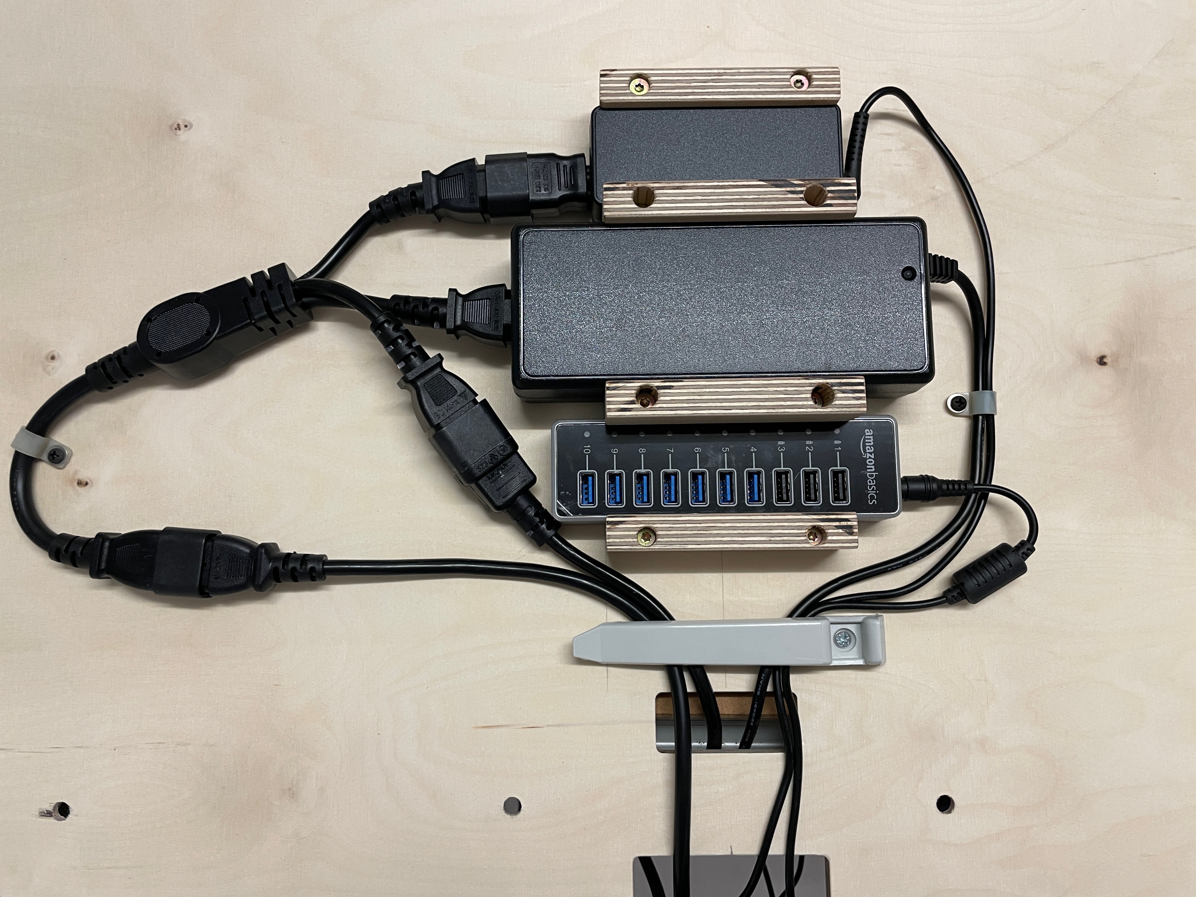
| The USB hub [1] and power supplies are mounted to the bottom of the "desktop", using some 3D printed brackets for the hub's power supply (FreeCAD, STEP), the MOZA yoke's power supply (FreeCAD, STEP) and a cable bracket (FreeCAD, STEP). |
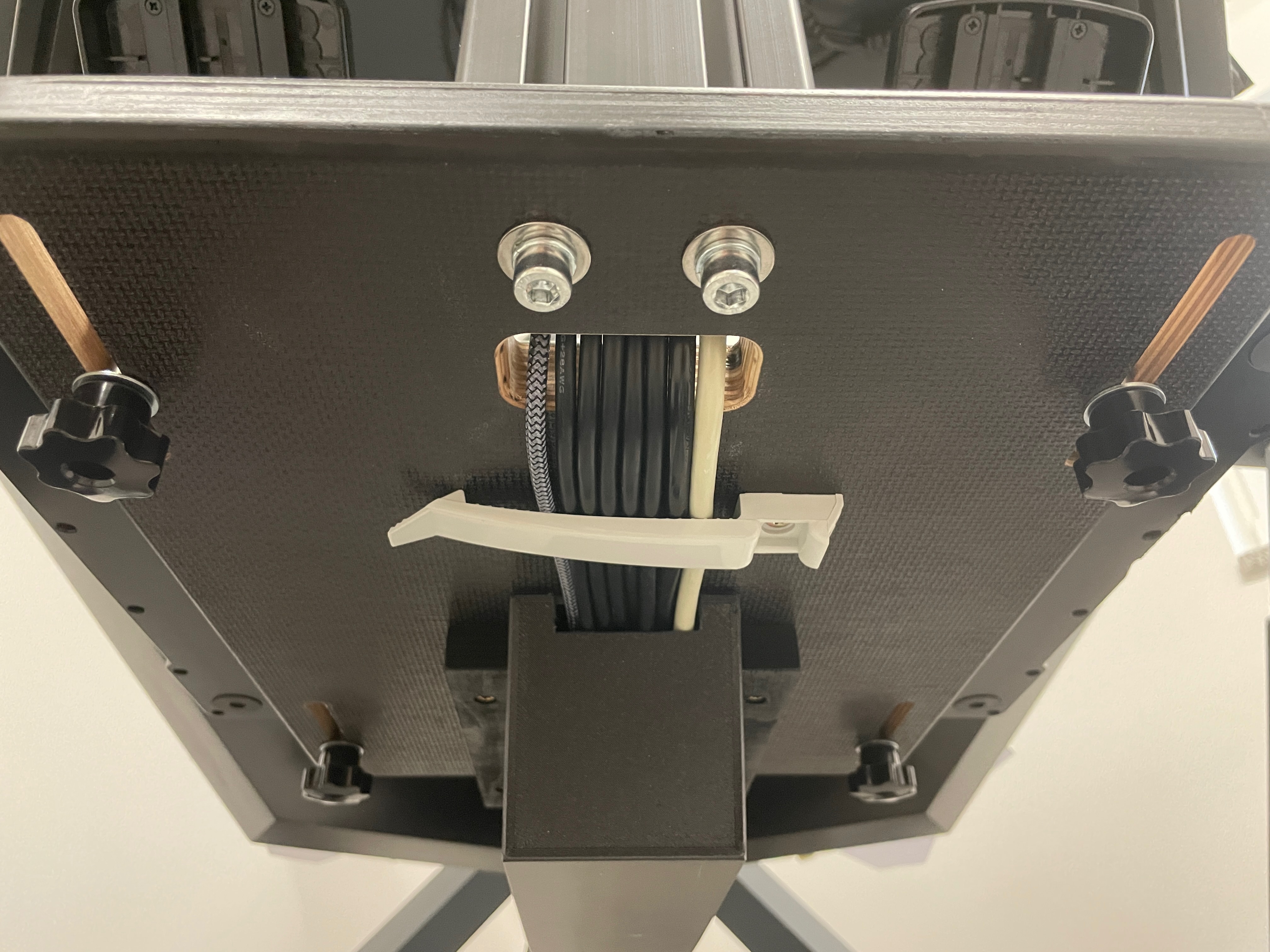
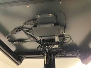 | A Y splitter power cable [2] distributes power from a 4-way power distributor [3] to the power supplies. The power distributor is mounted to the frame with a 3D printed plate (FreeCAD, STEP). Excess cable lengths are held in place with 3D printed hooks (FreeCAD, STEP). All cables that go from front to back are run through a cable duct [4] that goes from the "desktop" to the pedal plate. |
 | Below the pedal plate the cables are fed into the central spine of the "cradle"... |
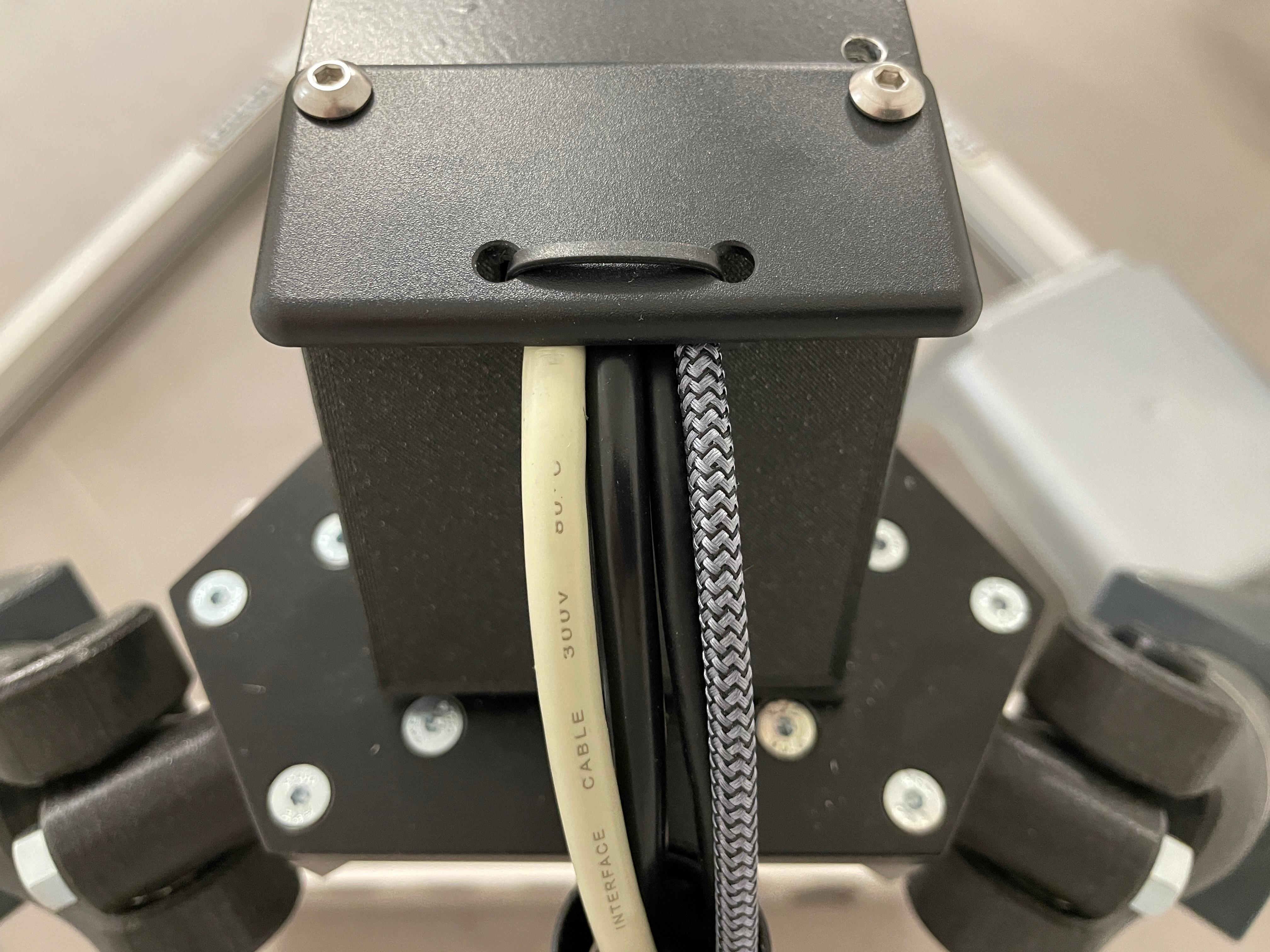
 | ...and come out at the rear end of the spine... |
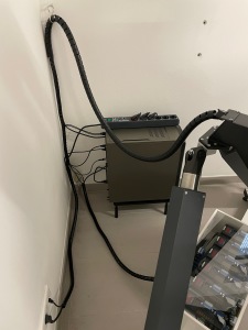 | ...from where a cable bundle tube [5] leads them to the PC and control box, respectively. Main power is supplied through a master/slave power strip [6], with the PC as the master. So turning the PC on/off also turns the rest of the hardware on/off. |
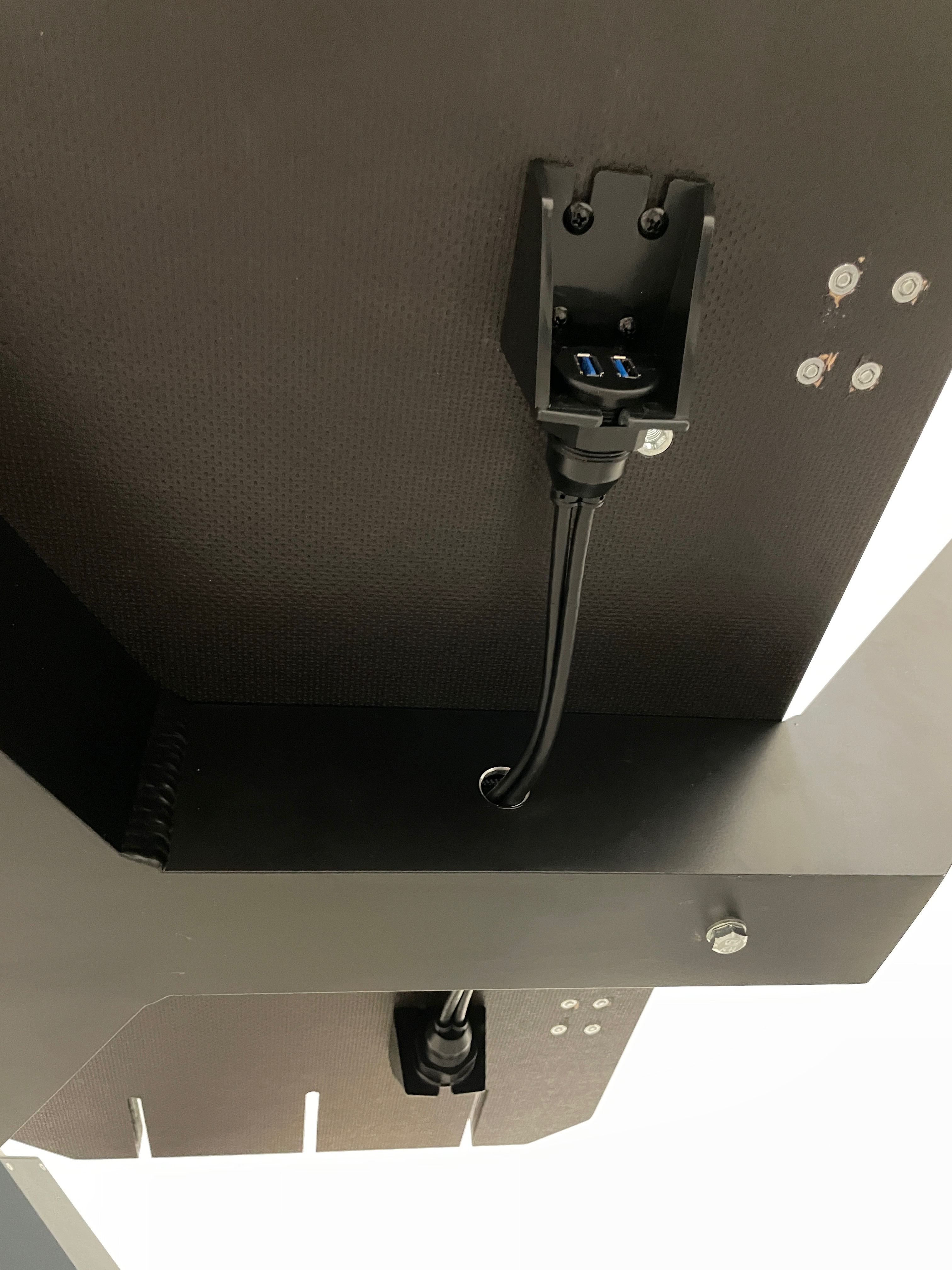
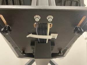
 | Under the seat plate I mounted two dual USB connectors [7] for connecting flight controls that are attached to the seat plate. |
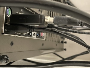 | With the actuator motors in motion, there was a problem with the motion encoder software losing the connection to the M4S controller. Assuming this was due to EMI picked up by ground loops in the USB cabling, I inserted a USB Isolator [8] between the PC and the M4S controller, which immediately fixed the problem. |
 | The cable of the VR headset is suspended from the ceiling using KIWI VR Cable Management [9]. |
Links
[1] https://www.amazon.de/dp/B0CKTM995J
[2] https://www.amazon.de/dp/B0BB6MFWFZ
[3] https://www.amazon.de/dp/B01LZKDQHG
[4] https://www.amazon.de/dp/B07PQXCBFH
[5] https://www.amazon.de/dp/B000L9QDCO
[6] https://www.amazon.de/dp/B00C255EQG
[7] https://www.amazon.de/dp/B07C4QK1HJ
[8] https://www.amazon.de/dp/B01N4WXYZJ
[9] https://www.amazon.de/dp/B07VPVXY2D
|