P6 Mods - Power
|
Home P6 Mods:
Board |
|
© 2024 KLS |
|
The DOFReality P6 control boxes have three power supplies [1]
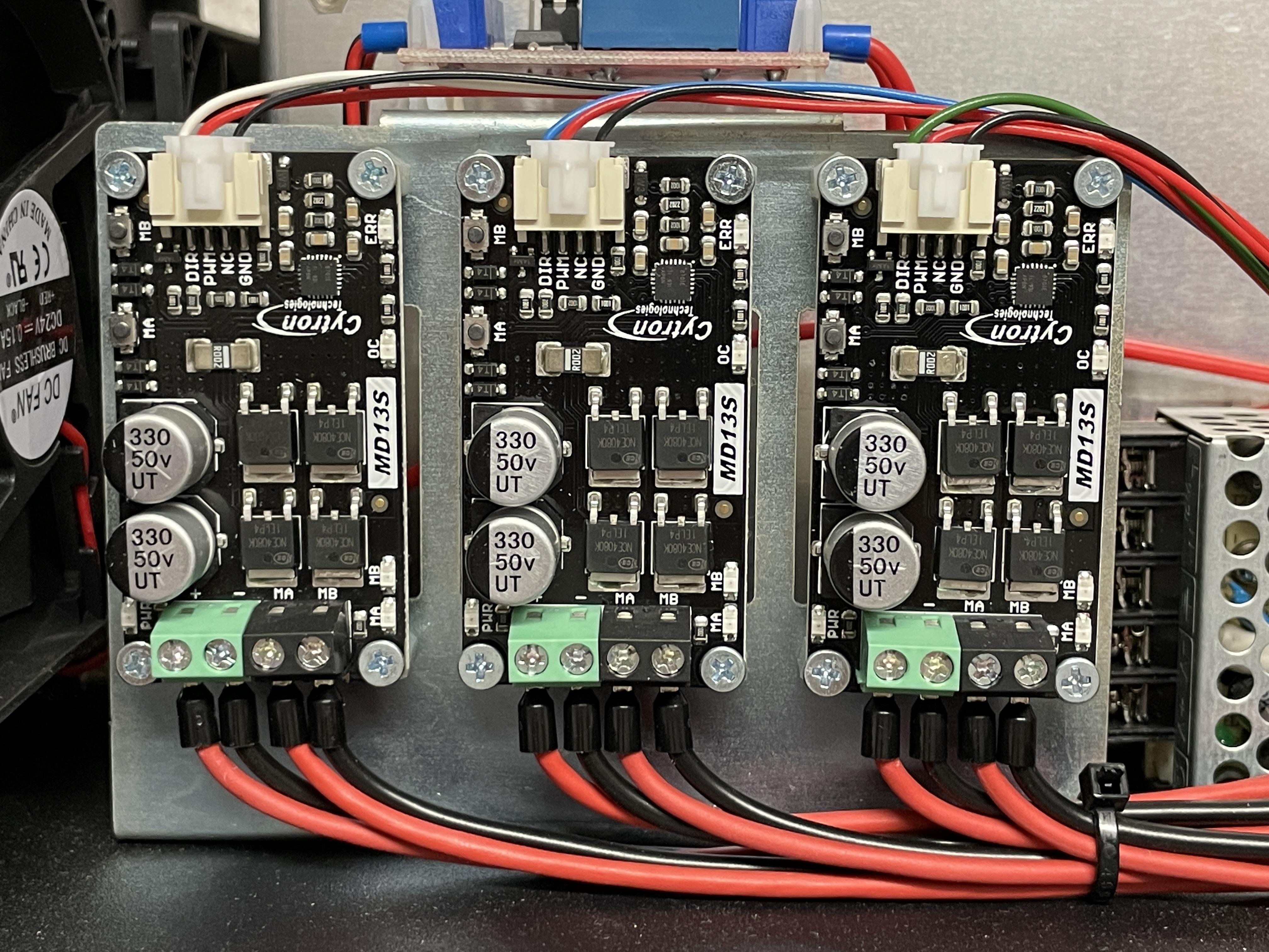
(one for each motor), that supply the motors via three MD13S [2] drivers.
After switching from the original to the SFU gears, my platform showed a strange
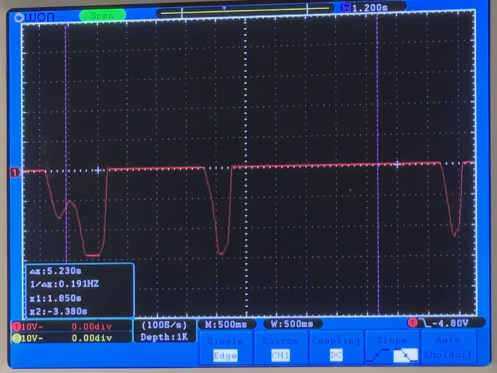
behavior. When a motor moved down and then up again, at the lowest point of the movement
it appeared as if it shortly lost power and made a "dip", which immediately broke immersion.
The following video was taken running the SMC3 utility in "Motion" mode:
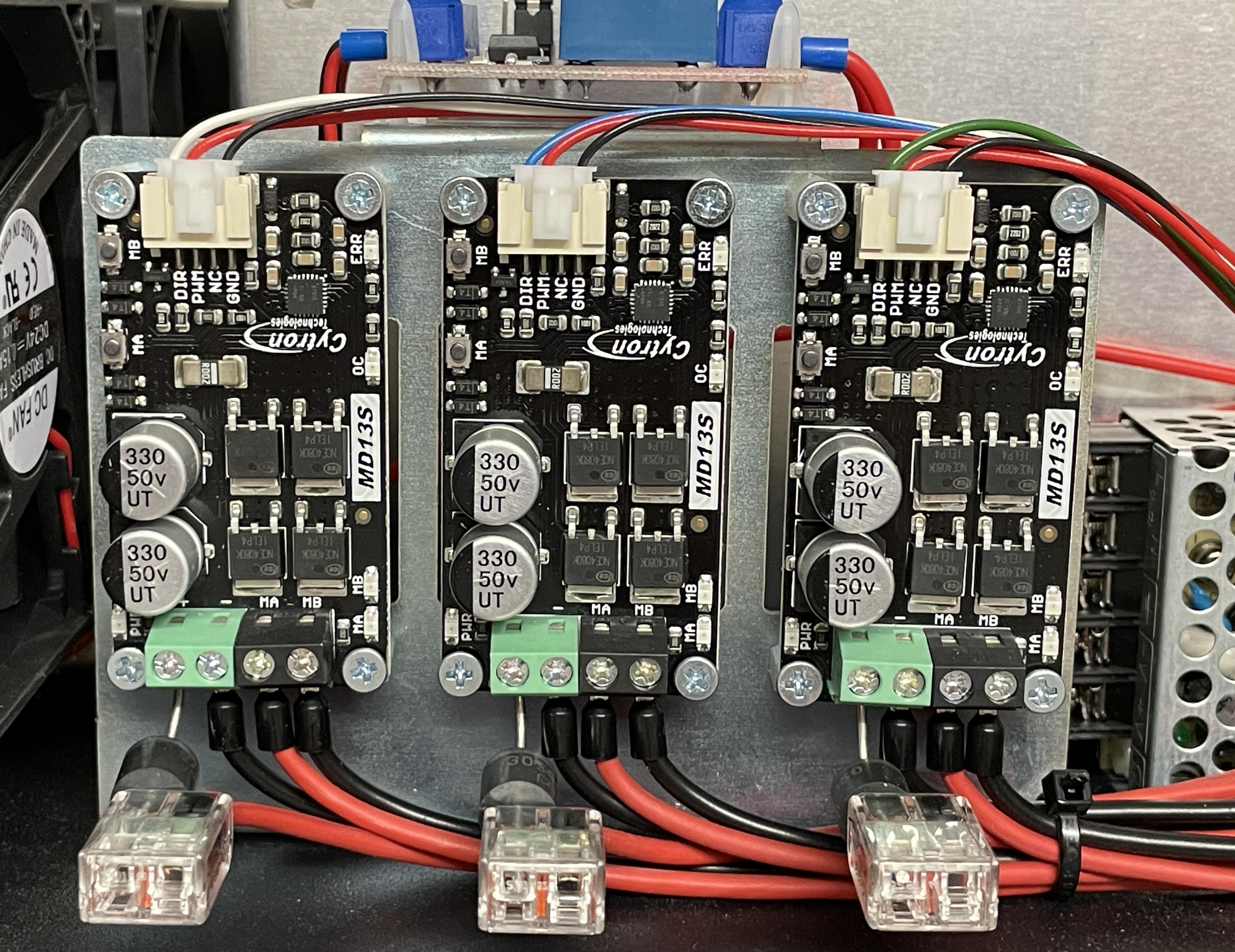
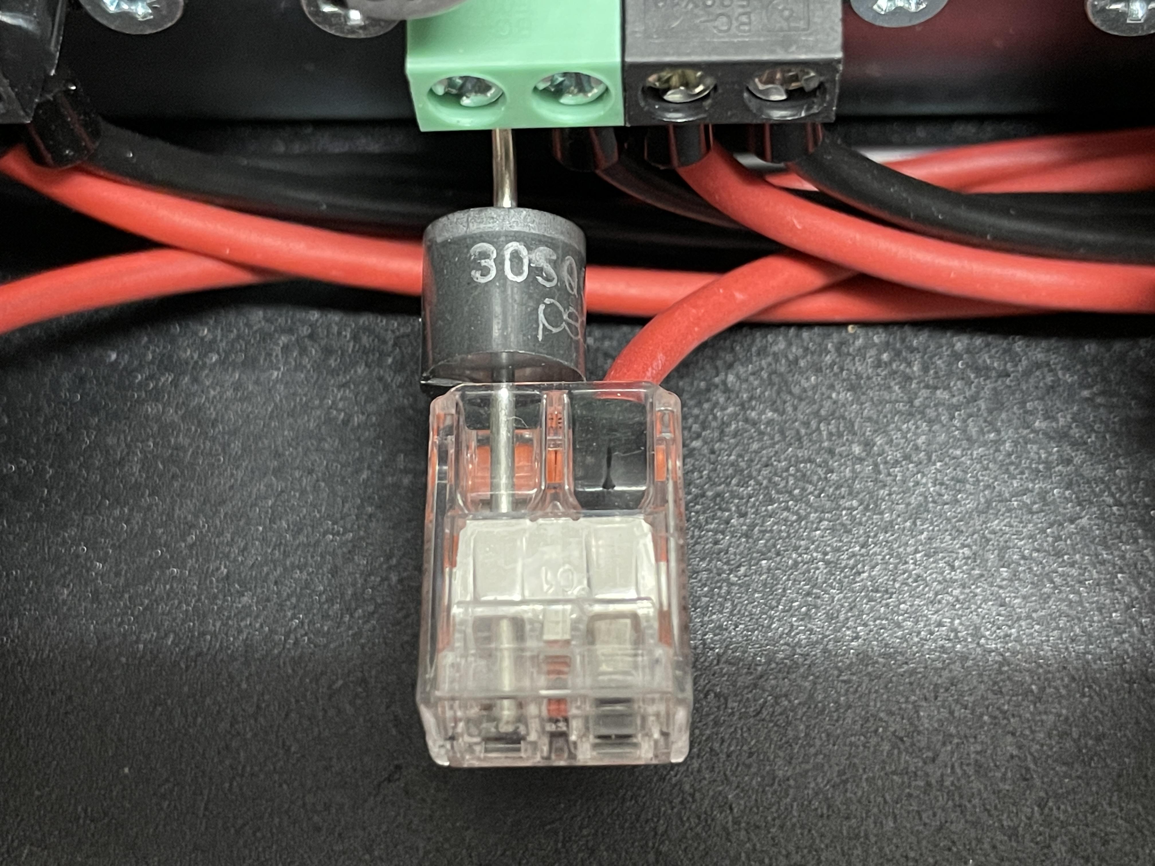
My first idea was that perhaps the power supply is too weak and can't support the sudden change of direction. But after some further investigation I stumbled across one feature of the MD13S drivers: "Regenerative Braking". This means that when the motor is driven by an external force, it works as a generator and delivers power back to the power supply. And as soon as that power exceeds 24V, the switching power supply tries to keep the voltage stable and regulates itself down, which results in the "dip". To fix this, I added three Schottky diodes (30A 50V) [3] between the power supplies and the driver. CAUTION: Make sure the control boxes are disconnected from main power before opening them!
With this modification (applied to both control boxes), the "dipping" is gone and the platform runs smoothly again. Mark Scheierman made a video [5] that shows in detail how to implement this fix:
[1] https://www.amazon.de/Meanwell-Biltron-Schaltnetzteil-geschlossene-Struktur/dp/B07SVH2H3G |


