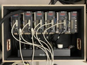
 | The original control box was nicely built, but would have been a bit too large for the way I wanted to mount it onto the base frame. |
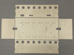 | I wanted the box to have a footprint of 600x300mm and a total height of 190mm. So I got me some 9mm plywood boards (1 of 610x310mm, 2 of 610x180mm and 2 of 300x180mm). I ordered them a little bit oversized, so I could cut them to the precise measurements myself (the hardware store has a +/-1mm tolerance). |
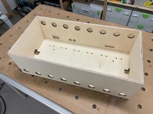 | After drilling and milling all the necessary holes and slots, the sides were glued together using Lamello [1] connectors... |
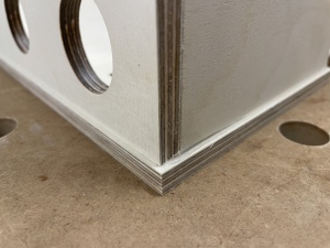 | ...and then glued onto the base plate. |
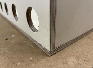 | Finally the base plate was milled to the exact outlines of the sides. |
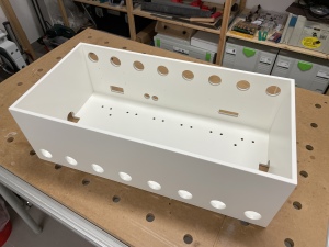 | Painted it white for good looks. |
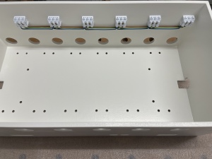 | Main power distribution uses Quick Connector Lustre Terminals. [2] |
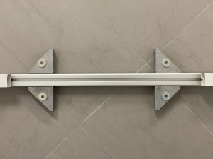 | Brackets [3] hold the control box to the rear bar of the base frame. |
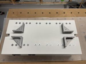 | Here's how the brackets are mounted to the bottom of the box. |
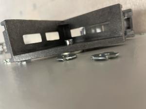 | 3mm washers are used between he brackets and the box, because the brackets are only 35mm high, while the aluminium profiles of the base frame are 40x40mm. Note the Drive-in nuts [4] used as mounting points for the drivers. They have to be hammered in pretty hard, which seemed a little brute for such an otherwise decent project. If I did this again, I would probably use something different here. |
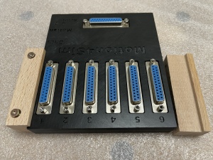 | To hold the Motion4Sim Controller [5] controller in place I used two pieces of wood, milled to an L-shape, mounted to the rear side.. |
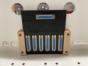 | ...where the controller slides in from the top. |
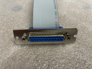 | A leftover D-SUB25 PC slot bracket, cut to the necessary length and with an extra hole drilled into it,... |
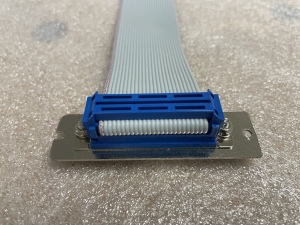 | ...with a piece of ribbon cable [6], a female connector [7] and proper screws [8]... |
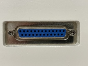 | ...mounted in the slot at the rear side... |
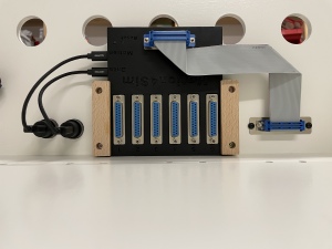 | ...was used to provide for an external connection to the handheld unit of the M4S controller. The other end of the ribbon cable uses a male connector [9] to plug into the M4S controller. This image also shows the USB B to USB A Panel Mount Feedthrough Adapters [10] and cables [11] I used to make the micro USB ports of the M4S controller accessible from the rear side of the box. In hindsight one of these (marked "Motion") would have sufficed, because the other aone ("Data") is only used when installing new firmware. |
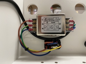 | Main power comes in through a cold device built-in plug with fuse holder and switch [12], goes through a Power Cable Filter [13] to avoid RFI... |
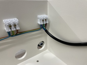 | ...and is connected to the power distribution line at the front of the box. |
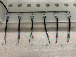 | A short cable connects each driver to main power. |
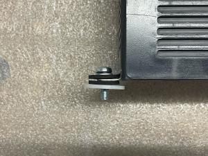 | To keep possible vibrations of the drivers from reaching the bottom of the box, rubber disks [14] are used to uncouple the mounting points. |
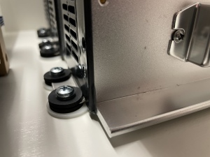 | The large plastic washers [15] are necessary to keep distance from the drive-in nuts that hold the brackets mounted to the bottom of the box. |
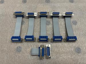 | These short ribbon cables with male [16] and female connectors [17]... |
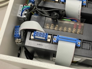 | ...allow the motors' sensor plugs to be connected in a way that reduces the overall height of the box. Note the Holding Posts&Nuts [18] that keep the plug from possibly falling off the connector through gravity. This image also shows the ribbon cables used to connect the data lines of the drivers to the M4S controller. |
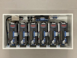 | Top view of the completed control box. Meanwhile I have extended the control box with a power supply and controls for motors with brakes. |
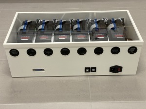 | To keep dust from falling into the box, but still be able to see the displays of the drivers, I used a 600x300x4mm Acrylic Glass pane [19], with a frame built from 20x10mm L-shaped plastic profile [20]. |
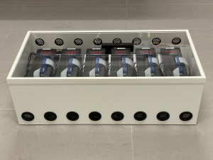 | Ventilation Grilles [21] in the front and rear side allow air to flow through the box. The holes for the grilles were made with a 35mm Forstner drill bit, but unfortunately I forgot to chamfer them a little on the outside, so that the grilles would go in all the way. Oh, well, so they stick out about a millimeter - not really noticeable from afar. |

